Creating SUB,MON,CON & DFX Files
Although Tools Exist in PSSE that Assist in Creating SUB,MON, and CON Files...
Power Flow>Linear Network>Create/Modify SUB,MON,CON Configuration Files
The Preferred Method is to Manually Create the SUB,MON, and CON Files with a Text Editor.
NotePad++ recommended (32 Bit)
Better yet... Use a Python script to create the files for you.
Creating the SUB File
The SUB File will Define at least two(2) Subsystems: MON & CON
And Perhaps Many More... Example: GEN,WIND,EAST,WEST,CITY etc.
By Example Using: savnw.sav
Located Here --> file:///C:/Program Files (x86)/PTI/PSSE34/EXAMPLE/
Go Ahead and Open the Case if You Like.
The savnw.sav Case Has: 23 Buses, 3 Areas, 4 Zones, 7 Owners
Areas = [1,2,5] Zones = [1,2,5,77] Owners = [1,2,5,11,22,55,100]
Each Subsystem Definition Begins with "SUBSYSTEM LABEL" and Terminates with an "END" Statement.
The SUB File Must also Terminate with an "END" Statement.
Note: The LABEL Must Be Enclosed in "Quotes" if it Contains Spaces.
Let's Define Two (2) Subsystems...
1) A Subsystem called "CON" that Includes all Buses in Area 5 and all Buses in Zone 1
2) A Subsystem called "MON" that Includes all Buses in Area 5 and all Buses in Zone 1
This May Seem Redundant and it is.
It is Common that the Contingency and Monitor Subsystem are the Same.
Just best practice.
Save the .sub File as --> some_name.sub
Frequently, you only want to Monitor Buses and Branches with Voltages in a Particular Range.
So Let's Define Two(2) Subsystems...
1) A Subsystem called "CON" that Includes all Buses in Area 5 and all Buses in Zone 1
2) A Subsystem called "MON" that Includes all Buses in Area 5, all Buses in Zone 1, that have Voltage >= 69kV
Simple Enough But.. BEWARE of This Trap!
The MON Subsystem Definition yields all Buses in Area 5 Plus all Buses in Zone 1 Plus all Buses >= 69kVIn Other Words...
The MON Subsystem will Contain All Buses in the Case >= 69kV
Not Just the Buses in Area 5 and Zone 1 that are >= 69kV
This is NOT what we Want!
Enter the JOIN Definition...
The JOIN Definition Begins with "JOIN LABEL" and ends with an "END" Statement.
Is Contained inside the SUBSYSTEM Definition.
The LABEL Name has no Particular Significance, It Can Be any String.
Again Note: The LABEL Must Be Enclosed in "Quotes" if it Contains Spaces.
So Let's Do it Right and Define the Two(2) Subsystems...
1) a Subsystem called "CON" that Includes all Buses in Area 5 and all Buses in Zone 1
2) a Subsystem called "MON" that Includes all Buses in Area 5, all Buses in Zone 1, that have Voltage >= 69kV
Done with .sub File Example...
The JOIN Definition does a Logical "AND" of Each Unlike Element Type in the JOIN Block.
That is Why there is Separate JOIN Blocks for Each Element Type. (AREAS and ZONES in this Example)
If a Bus is in Area 5 AND is also >= 69kV... It Will Be Included in the AREA_GROUP and added to the MON Subsystem.
If a Bus is in Zone 1 AND is also >= 69kV... It Will Be Included in the ZONE_GROUP and added to the MON Subsystem.
Save the .sub File as --> some_name.sub
The Join Block can be Tricky, So be Careful.
Consider the MON Subsystem Definition Below...
This MON Subsystem will yield a much Different Result.
The JOIN Definition does a Logical "AND" of Each Unlike Element Type in the JOIN Block.
If a Bus is in Area 5 AND is in Zone 1 AND is also >= 69kV...
It will Be Included in GROUP_1 and added to the MON Subsystem.
Check Out this Subsystem Logic Worksheet.
Creating the MON File
The MON File will Specify what Branches and Buses are Monitored during Contingency Analysis.
The MON File must Terminate with and "END" Statement.
Below is a Common Example...
The Token "3WLOWVOLTAGE" is included to Monitor Flows on all windings of a Subsystem 3WXfmr...
Even if the winding is Connected to a Bus that is Not Part of the Subsystem.
MONITOR TIES is usually Included...
Exception may be When Performing Double Contingencies, To Decrease the Number of Branches to Monitor.
MONITOR VOLTAGE RANGE is always Included, Although the Low and High Limits Don't seem to Matter...
All MON Subsystem Bus Voltages will be Included in the Resulting .ACC File...
The Extra "END" Statement is Included for Good Measure.
Save the .mon File as --> some_name.mon
Creating the CON File
The CON File will Specify what Branches will be Outaged During Contingency Analysis.
The CON File must Terminate with and "END" Statement.
Below is a Common Example using the PSS®E Automatic Contingency Specification...
Use SINGLE for N-1
Use DOUBLE for N-2
The Token "3WLOWVOLTAGE" is Included to Outage all windings of a Subsystem 3WXfmr...
Outaging TIES is usually Included...
Exception may be When Performing Double Contingencies, To Decrease the Number of Branch Combinations to Analyze.
The Extra "END" Statement is Included for Good Measure.
Save the .con File as --> some_name.con
Creating the DFX File
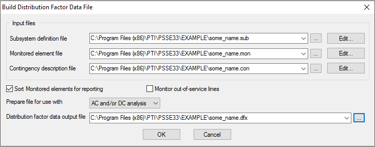
The DFX File is Created Inside PSS®E
Open savnw.sav with PSS®E
Go To: Power Flow>Linear Network>Build Distribution Factor Data File (DFX)

Hit the OK Button...
The DFX File is Created and saved as some_name.dfx.
Last Step: Run the Analysis
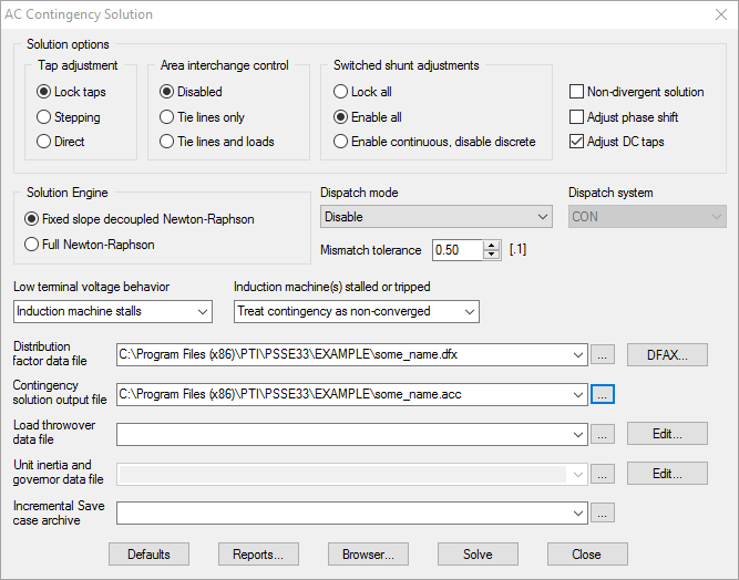
The Analysis is Run Inside PSS®E
Open savnw.sav with PSS®E
Go To: Power Flow>Contingency, Reliability, PV/QV Analysis>AC Contingency Solution (ACCC)

Hit the Solve Button...
Analysis is Run with Results saved in the some_name.acc File.
It is up to you to Analyze the Results...
You can get Text Reports inside PSS®E.
Better Yet... Create a Python Script to Analyze the Results.


